Symmetry
Halve or quarter a symmetric model without losing accuracy.
If a part, together with its supports and loads, is mirror-symmetric about a plane, you only need to compute one half, with no loss of information. On the cut face you apply a symmetry constraint: the face may not move out of the plane, but is free to move within it. Each additional symmetry plane halves the model again: two planes give a quarter, three an eighth, always by the same rule.
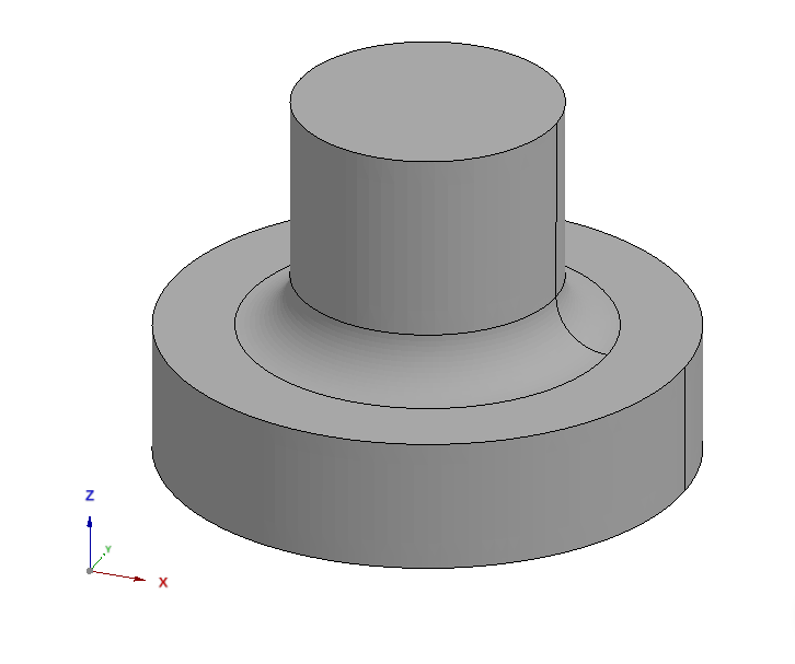
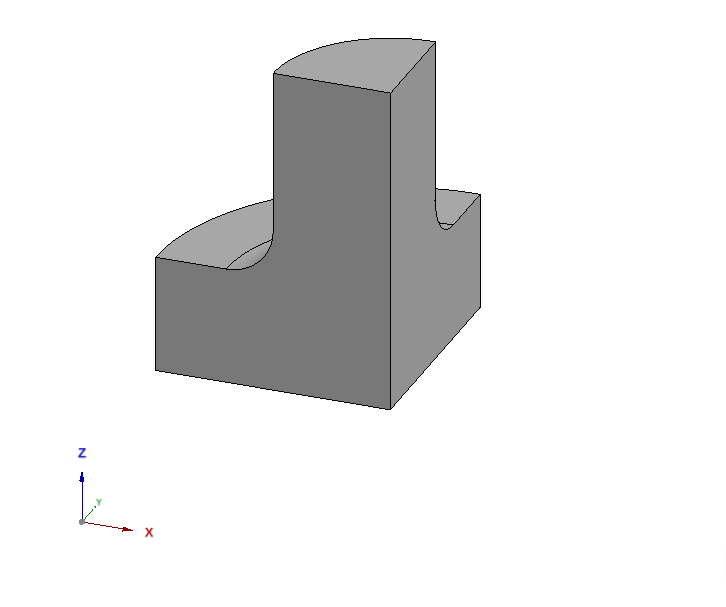
Why it works
When geometry, material, supports, and loads all share a symmetry plane, the result must be mirror-symmetric too. The omitted half then behaves exactly like the mirror image of the computed half: nothing crosses the cut plane that would break the symmetry. You replace the omitted half with the correct symmetry constraints on the cut face; the full solution follows by mirroring.
The constraints on the cut faces
Mirror symmetry means no point on the cut face can move out of the plane: a displacement normal to the plane would break the symmetry, because the mirrored half would move exactly the opposite way. So on the cut face we lock the displacement normal to the plane. Within the plane, the material must remain free to move. A symmetry plane acts like a frictionless support: held normal to the plane, sliding along it.
When symmetry is not allowed
You may only use symmetry when every ingredient has it: geometry, material, supports, and loads must all mirror the same plane. If even one of them breaks the symmetry, the result is wrong. The most common trap is a symmetric geometry with an asymmetric load, such as a shear force across the plane. The symmetry constraint then gives a wrong answer.
Benefits
Fewer elements mean less compute time and less memory (see Computation Time). One plane halves the model, two planes quarter it, without any loss of accuracy.
A second, often overlooked benefit: the symmetry planes also provide a clean support. Because each cut face is held only in its normal direction and stays free within the plane, it removes rigid-body motion without restraining the material's lateral contraction. This anchors the part without the artificial constraint stresses that a fully fixed face would introduce.
Pitfalls
Modal and buckling analyses: A symmetric model finds only symmetric mode shapes. Antisymmetric modes, often the critical ones in buckling, are missed. Run modal and buckling analyses on the full model unless you are sure the mode you want is symmetric.
Over-constraining: On the symmetry faces, only the displacement normal to the plane may be locked. If you accidentally lock all directions, you suppress the lateral expansion that must stay free there. The model does not become unsolvable, just too stiff: it runs cleanly but returns an artificially stiffened result with inflated stresses at the cut face.
Static under-constraint: Symmetry constraints lock only the motion normal to each plane; within the plane they allow displacements and rotations. They therefore do not replace the actual supports. Make sure the symmetry planes and the real supports together fix all six rigid-body degrees of freedom. Two symmetry planes, for example, take five of them; a real support must take the sixth, otherwise the system is singular and the solve fails.