STEP Surfaces as Boundary Conditions: 51% More Precision in FEM Simulation

If you regularly set up FEM simulations, you know the problem: boundary conditions, meaning forces, pressures, or supports, need to be applied to specific surfaces or edges of the CAD model. In practice, this often means clicking through faces, assigning numbers, and hoping everything still holds together after a geometry change. It is error-prone, hard to reproduce, and wastes time on every recurring analysis.
There is a more elegant way: define boundary condition surfaces as standalone STEP files and load them directly into the simulation. What this means in practice, what benefits it delivers, and why the results become more realistic as a consequence: we walk through it using a real example.
The Concept: Surfaces as Separate STEP Files
The core idea is simple but effective. Instead of placing boundary conditions on existing surfaces of the solid body, the relevant regions, meaning the zones where forces are applied or supports defined, are provided as their own STEP files.
These files contain no solid bodies, only surfaces. They are created in the CAD system, named cleanly, and loaded into the simulation environment alongside the actual part. Upload order does not matter. What matters is that the surface sits geometrically where the boundary condition acts in reality.
The result is a clean separation: the part itself stays unchanged, and boundary condition definition is driven by external surfaces, directly from the CAD, without detours through face numbers or manual selection inside the simulation environment.
Practical Example: 51% Difference Through Realistic Load Application
To make the effect tangible, we ran a concrete example. The part was kindly provided by Axel Fett of Protosolid.
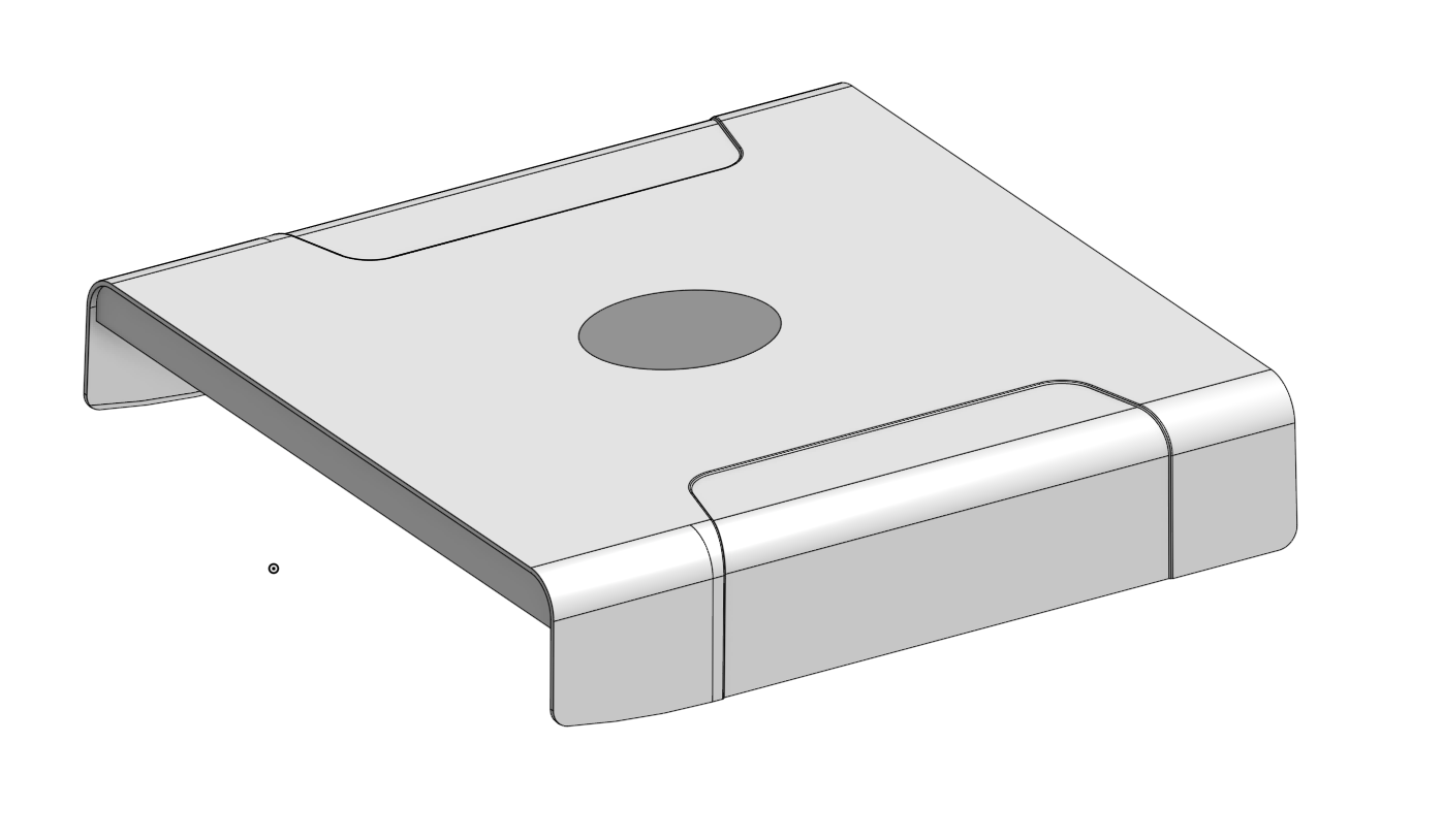
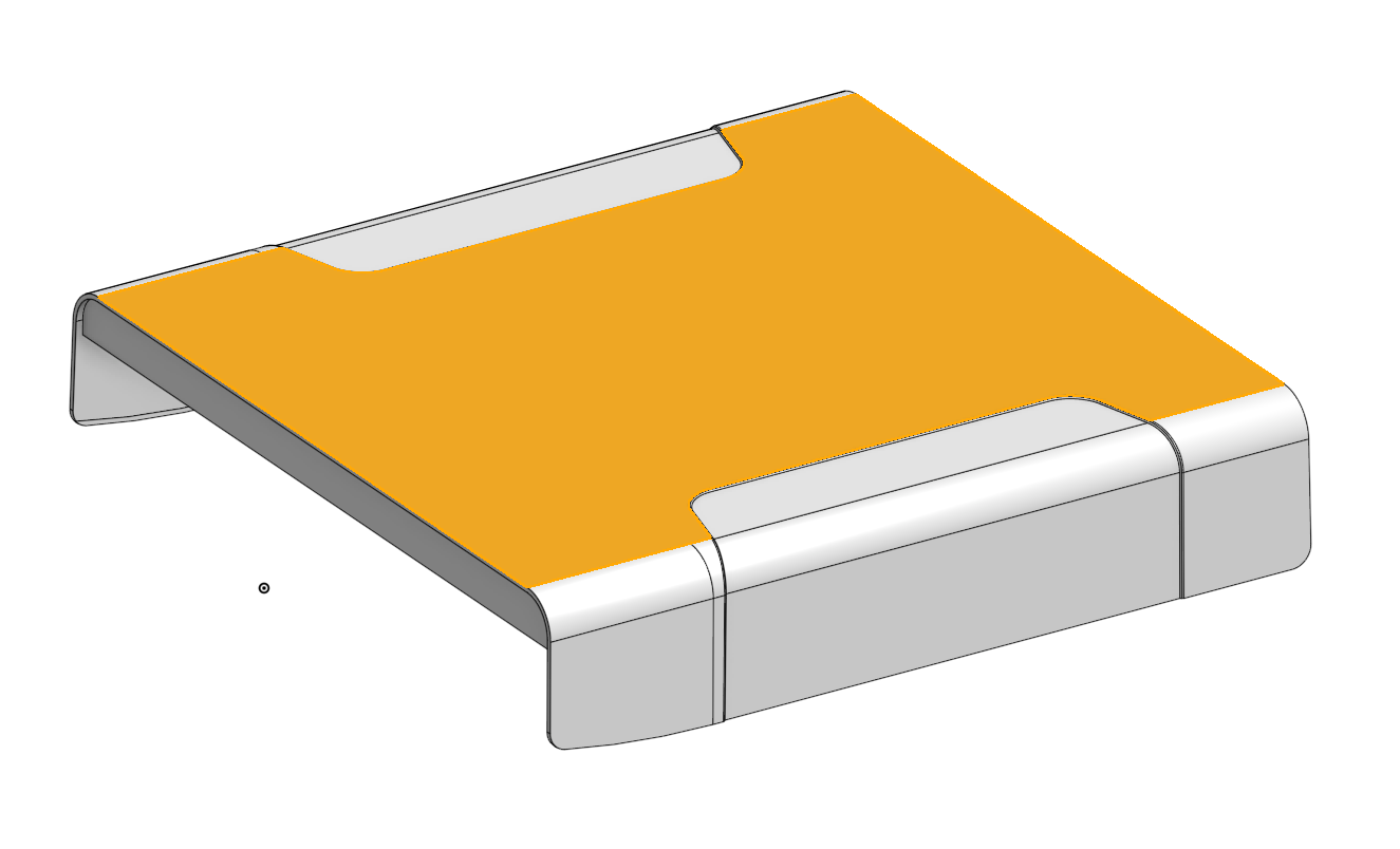
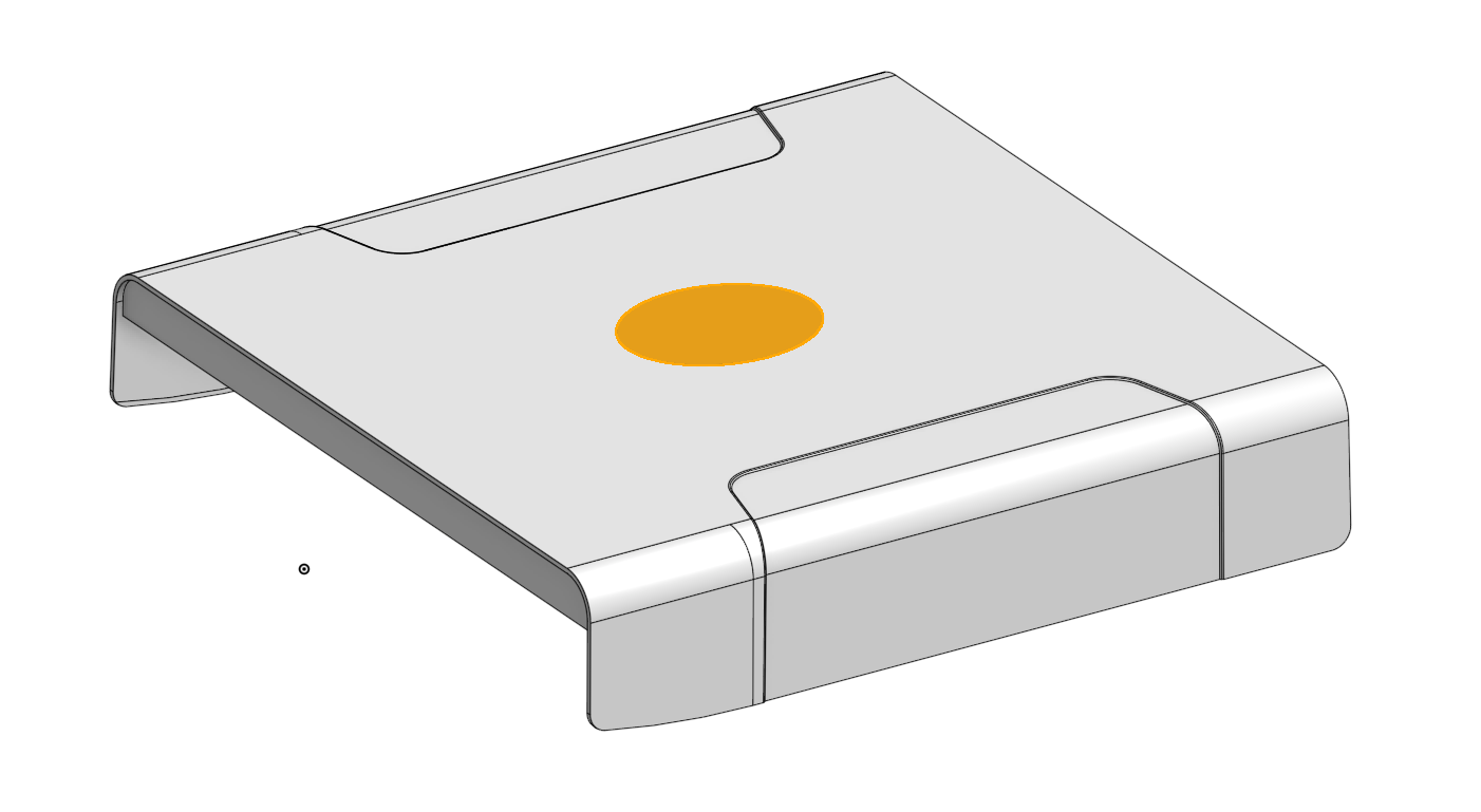
The load case: A person weighing 100 kg steps on the part. The bottom surfaces are fixed. We calculate what stresses arise in the part. Both load cases use the identical mesh.
Two variants are compared:
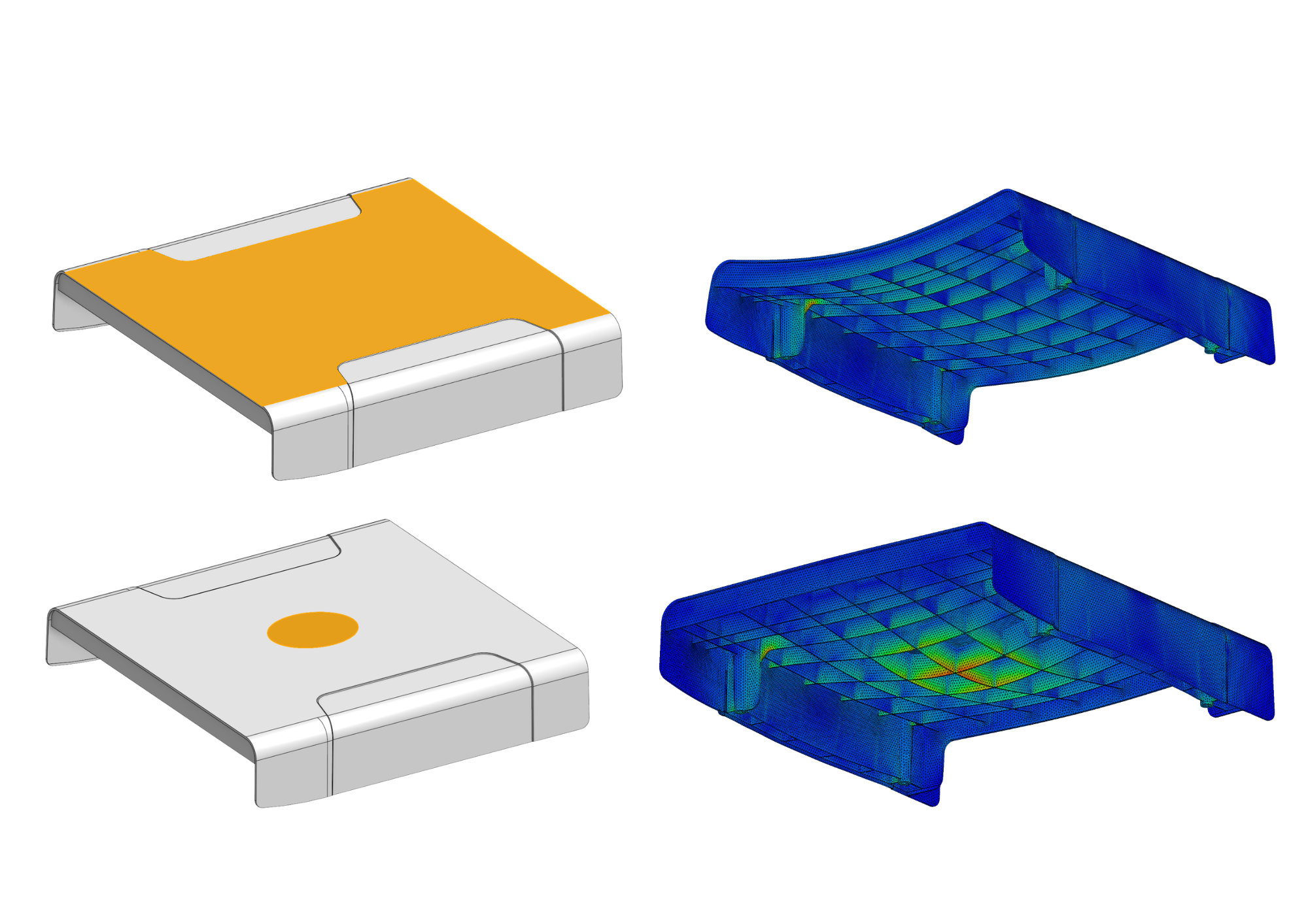
Case 1 – Force on an existing CAD face: The weight force is applied directly to an existing flat face of the part model. Result: a maximum stress of around 18 MPa.
Case 2 – Force through a STEP boundary condition surface: The same force is applied through an oval surface defined as a STEP file. This surface represents the actual footprint far more realistically. Result: a maximum stress of around 27.7 MPa.
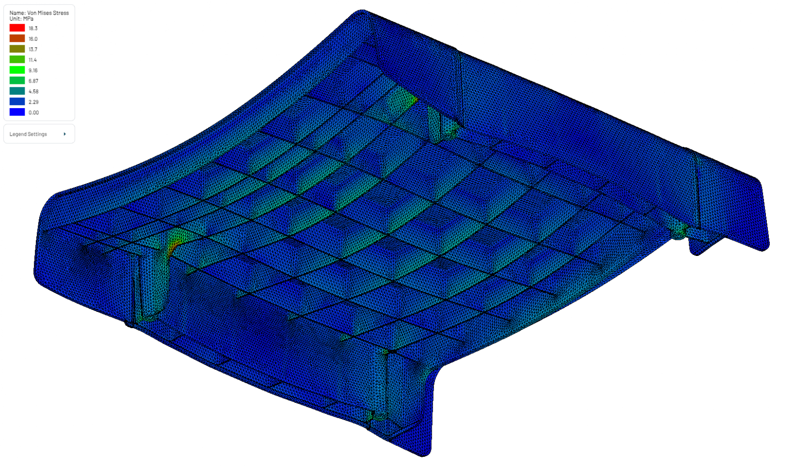
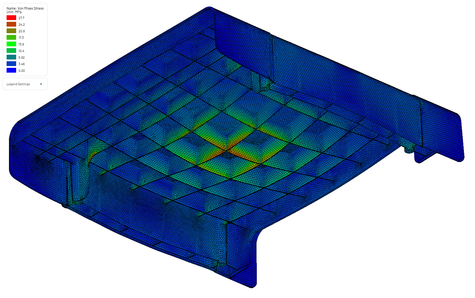
That corresponds to an increase of about 51 percent, driven purely by the more realistic definition of the load surface, with identical part and identical total force. More importantly: the location of peak stress shifts.
This result illustrates how strongly the method of load application affects simulation results. Applying forces broadly to large, flat surfaces can significantly underestimate the actual stresses that occur. Targeted load surface definition via STEP files fixes this.
We walk through the entire workflow, from file upload through script creation to result evaluation, in our YouTube video on the topic.
What Are the Benefits of This Approach?
More Realistic Simulation Results
The most obvious benefit is in result quality. Real load application is rarely uniform across an entire part surface. Contact surfaces, support zones, sealing regions, or, as in the example, a person's footprint, have a specific shape and position. Defining these regions as their own surface in CAD and passing them to the simulation as a STEP file mirrors physical reality much more closely. That yields more meaningful stress, deformation, and safety values.
CAD-Based Boundary Condition Definition
The boundary condition surfaces are created where designers are most at home: inside the CAD system. There is no more need to hunt for the right face in the simulation environment, assign numbers, or switch between views. Definition happens intuitively and visually, directly on the 3D model. That reduces errors and lowers the barrier for users who mainly work in CAD.
Automation and Reproducibility
This is one of the biggest levers for everyday practice. If STEP surfaces are named cleanly and consistently, a simulation script written once can be applied across different geometry variants, without walking through the model setup every time. The script references boundary conditions by surface filename, not by geometry-dependent numbers.
For companies running similar analyses regularly, whether across product series, customer variants, or standard verifications, this delivers substantial time savings. Recurring simulations can be built into standardized, automated workflows that produce consistent and traceable results.
Decoupling Geometry and Boundary Conditions
When the part changes, through a design iteration or a new variant, boundary conditions do not automatically need to be redefined. As long as the STEP surfaces still fit geometrically and keep their naming, the existing simulation script continues to work. Boundary condition definition is decoupled from part geometry, making the simulation setup much more robust against change.
Better Collaboration Between Design and Analysis
In many companies, design and analysis teams work separately. Handing over simulation boundary conditions is a typical bottleneck: the designer knows where forces are applied but does not always have a way to transfer that information into a simulation-ready format. The analysis engineer, in turn, has to first get up to speed on the geometry.
STEP boundary condition surfaces close this gap elegantly. The design team defines the relevant surfaces directly in CAD and provides them as named STEP files. Analysis can use these files immediately, without follow-up questions, without interpretation, without additional coordination.
When Is This Approach Especially Worthwhile?
Not every one-off analysis justifies the extra effort of creating separate surfaces in CAD. The approach is especially worthwhile in the following scenarios:
Companies running recurring simulations with changing geometries, such as variant or product-series development, benefit most. A simulation workflow defined once can be reused again and again with new geometries and matching boundary condition surfaces.
For complex or non-trivial load application regions that cannot be sensibly mapped to existing CAD faces, the approach delivers more realistic results. Typical examples include contact surfaces, footprint areas, localised pressure zones, or regions with defined fixation.
Teams building internal analysis standards, or maintaining established standard processes, can use named STEP surfaces to create a continuous, traceable, and automatable process chain.
And anywhere design and analysis are organisationally separate, the approach simplifies handover and reduces coordination overhead.
Conclusion
Defining boundary condition surfaces via standalone STEP files is a relatively small adjustment to the simulation workflow, with outsized impact. Results become more realistic, because loads and supports act where they actually act in reality. At the same time, efficiency increases, because simulation workflows become automated, standardized, and robust against geometry changes.
In our practical example, the more realistic load surface alone produced a 51 percent higher stress value, a difference that in part design can decide between safety and failure.
Anyone running FEM simulations regularly, and caring about robust results and efficient processes, should consider this approach.